

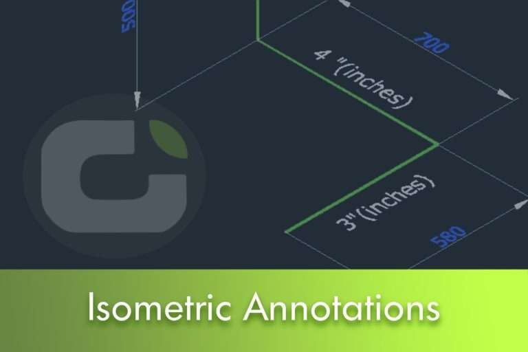
Write it down isometric drawings can be misleading: the drawing is in isometry, but the text and dimensions do not follow this orientation by default. To obtain annotations that are consistent with the isometric view, prepare text styles at ±30° and corresponding dimension styles, and apply skew to extension lines where necessary. Below is a simple guide to creating isometric text and dimensions (including the use of the DIMEDIT command with the OBLIQUE option).
Isometric text
First, create two text styles in the Text Style dialogue box. Use an oblique angle of 30° for one style and -30° for the other. 

Next, create text (single line or multiline) using different combinations of styles and angles and then change the rotation to 30° or -30° depending on where you want to place it. See the following image for reference.


Isometric dimensioning
And the quotes and text - do they appear correctly? Usually not. The drawing looks isometric, but the annotations don't. So how can you create isometric annotations?
Here too, you have to create two styles in the Dimension Style Manager dialogue box. One of the styles uses the 30° text style and the other uses the -30° style. Now insert an aligned dimension. Note that the extension lines of the placed dimension are not perpendicular to the blue line. So let's make a small adjustment.
Activate DIMEDIT [Enter], choose the OBLIQUE option and enter 30 or -30 as the angle of obliquity (depending on the orientation of your dimension).

Command: DIMEDIT
Enter the type of quota editing [Home/New/Rotate/Oblique] : O
Select objects: 1 found
Select objects:
Enter the angle of obliquity (press ENTER for none): -30
Summary:
Create two text styles at ±30°, use them in two dimension styles, place aligned dimensions and apply DIMEDIT > OBLIQUE with ±30° to the extension lines to align the annotations with the isometric view.

 English
  Portuguese
  Spanish