

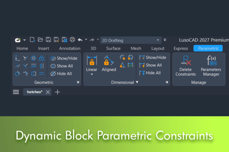
As we have already seen in articles about system variables such as Association of Associations, VISRETAIN or XREFOVERRIDE, many of LusoCAD's most powerful features exist to reduce repetitive work and minimise errors. Parametric constraints follow the exact same philosophy: instead of modifying objects manually every time a revision occurs, you can define rules that automatically control the behaviour of the geometry.
With the introduction of Parametric Constraints in Dynamic Blocks, LusoCAD enables the creation of smart components that can not only be adjusted, but also respect previously defined geometric and dimensional relationships. The result is greater control over revisions, increased consistency between drawings and a significant reduction in time spent on modifications.
What are Parametric Constraints?
Parametric constraints allow you to define rules between drawing objects.
Instead of drawing elements that operate independently, it is possible to create relationships that determine how the geometry should behave when a change occurs.
For example:
- Two lines can remain parallel
- Two circles can remain concentric
- One point may coincide with another
- A length may remain fixed
- An angle can be set to a specific value
These relationships make geometry smarter and more predictable.
What Changes When Applied to Dynamic Blocks?
Parametric constraints could already be used in the geometry of a drawing. The big new feature is the ability to integrate them directly into dynamic blocks.
This means that a block is no longer just a set of grouped objects.
Start functioning as an intelligent rule-based component.
When a parameter is changed:
- The geometric relationships are maintained
- The dimensions adjust automatically
- The shape of the block remains consistent
Instead of redesigning elements, you simply alter the defined parameters.
How to Edit a Dynamic Block
To add parametric constraints, the block must be opened in the Block Editor.
You can do it in two ways.
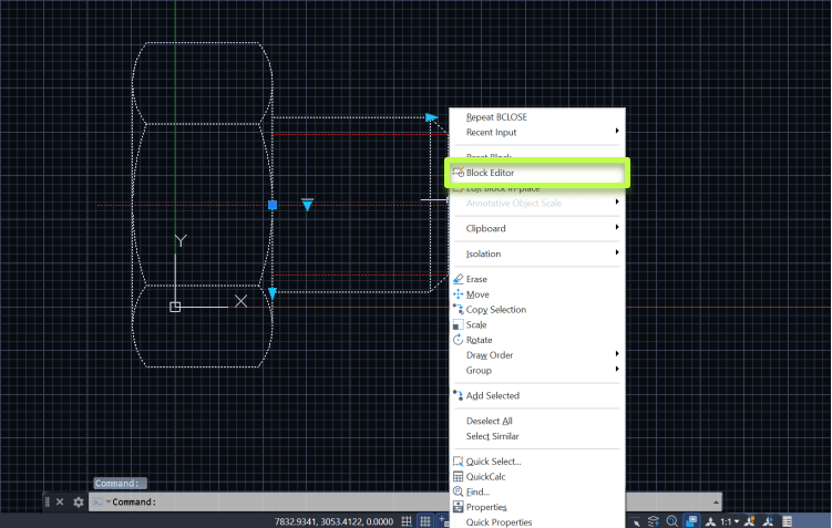
Method 1: Select the Block
Select a block reference in the drawing and open the Block Editor.
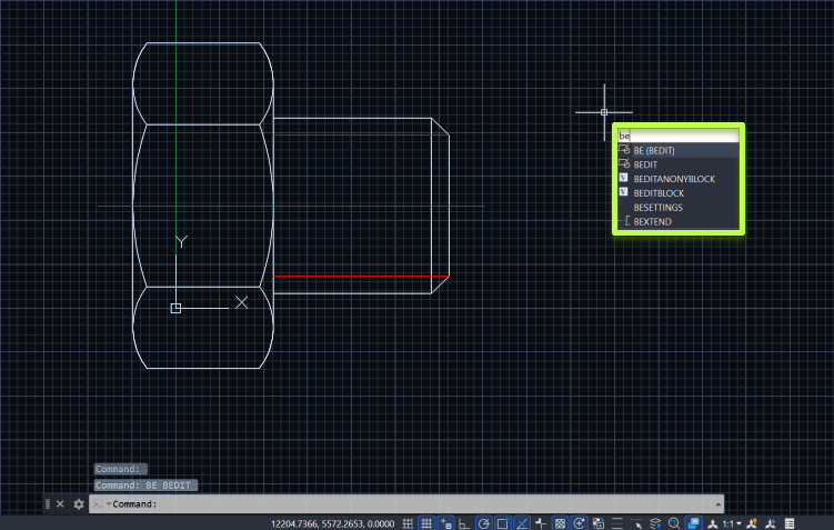
Method 2: Use the Command Line
Write
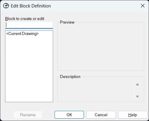
Then select the block you want from the list provided.
The Block Editor will open and you can begin defining the necessary constraints.
Types of Restrictions Available
Restrictions are generally divided into two categories.
Geometric Constraints
They govern the relationships between objects.
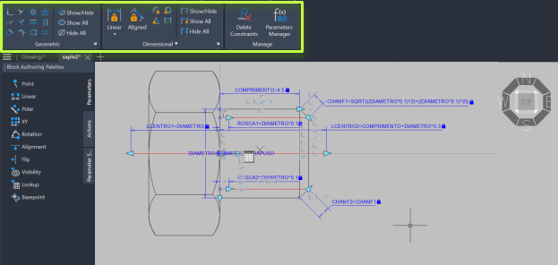
Examples
- Parallel
- Perpendicular
- Concentric
- Coincidental
- Horizontal
- Vertical
- Tangent
These constraints ensure that the geometry maintains the correct relationships during changes.
Dimensional Restrictions
They monitor specific values.
Examples
- Greetings
- Distances
- Lightning
- Diameters
- Angles
When one of these values is changed, all the associated geometry is updated automatically.
1. Less Manual Labour
One of the biggest advantages is the reduction in manual adjustments.
Without parametric constraints, a simple change to the size of a component may force you to:
- Move rows
- Adjust arches
- Reposition circles
- Update dimensions
With the defined restrictions, the block itself adapts automatically.
This makes revisions much quicker.
2. More Consistent Geometry
Traditional blocks already allow actions such as:
- Stretch
- Move
- Rotate
- Mirror (Flip)
- Change visibility
However, they do not always guarantee that the geometric relationships are maintained.
Parametric constraints add an extra layer of control.
For example:
- An axle remains centred
- A hole remains concentric
- Two faces remain parallel
Even after several changes.
3. More Efficient Global Updates
When a change is made within the block definition, all references to that block can be updated throughout the drawing.
Imagine a detail that is used fifty times in a project.
Instead of locating and editing each instance individually:
- Open the notepad
- Adjust the parameters
- Save the change
All references may reflect the new definition.
This significantly reduces the risk of forgetting elements during a review.
4. Flexibility at the Instance Level
Not all alterations need to affect every block.
One of the advantages of dynamic blocks is the ability to expose parameters to the user.
These parameters can be changed directly in the drawing space by:
- Grips
- Properties
- Parametric values
In this way, a single instance can be adjusted without modifying the main block definition.
5. Better Control over Complex Projects
As drawings grow, the management of repetitive components becomes increasingly difficult.
Parametric constraints help maintain:
- Geometric consistency
- Dimensional accuracy
- Project consistency
- Lower probability of error
They are especially useful in:
- Mechanical projects
- Metal structures
- Industrial equipment
- Modular components
- Standardised block libraries
Practical Example: A Fastener
Imagine a mechanical drawing that uses the same fastener in several places.
Within the Block Editor, rules can be defined such as:
- The central axle remains aligned
- The circles remain concentric
- The side faces remain parallel
- The length is controlled by a parameter
- The diameter is controlled by another parameter
When it is necessary to change the component:
- The user only changes the parameters
- The geometry adapts automatically
- The form remains correct
- All references can be updated together
The result is a much faster and more reliable process.
An Important Note
Although the changes made inside the block update its internal geometry, elements external to the block still require verification.
For example:
- Adjoining walls
- Connection lines
- External dimensions
- Other related elements
As with any design change, a final check remains recommended.
Feature Availability
The creation of parametric constraints in dynamic blocks is available only in the edition:
LusoCAD Premium
Users of the other editions can view and use blocks that already contain parametric constraints, but they may not have access to the creation and editing tools described in this article.
Conclusion
Parametric constraints in dynamic blocks represent a major step forward in the creation of smarter CAD components. By combining the flexibility of dynamic blocks with geometric and dimensional rules, LusoCAD allows you to create more robust libraries, speed up revisions, and reduce errors in complex designs.
For teams that work regularly with repetitive elements, standardised components or frequent revisions, this feature can translate into a significant improvement in productivity and drawing quality.

 English
  Portuguese
  Spanish